
SDN using OVN and OVS (Part 4)
Learn about implementing Software Defined Networks using OVN and openvswitch
Part Four of this series will explore configuring our SDN via ovn-northd to create virtual networks and our first NFV (network virtual function), a logical router.
Through parts 1-3, we have built up our understanding of ovn-northd (with Northbound/Southbound DB) as well as Open vSwitch and ovn-controller. Hopefully, we remember that ovn-controller applies the configuration we load into ovn-northd on the local instance of Open vSwitch for a virtualization host.
As with the previous parts, I am not providing the end-to-end steps, as this is still aimed at demystifying each area of building an SDN.
Logical Switches
Logical Switches function similarly to physical layer-2 network switches. Each Logical Switch is an L2 broadcast domain with ports (similar to Ethernet ports) for connecting VMs and other devices, and they are analogous to cloud-native solutions like an Azure Virtual Network.
You can refer to Logical Switches and Virtual Networks interchangeably as they represent the same concepts.
To create, update, and remove Logical Switches in ovn-northd, you use the ovn-nbctl ls-... commands. For example:
ovn-nbctl ls-add my-switch

This will create a new Logical Switch in OVN (called my-switch), which will be distributed via the Southbound DB to all Libvirt hosts running ovn-controller. Note that we don't have to specify where to create the switch; it's automatically synchronized to every host by ovn-controller (running on each host), so any connected VM will be able to communicate on it regardless of the physical network topology in between.
Logical Switch Ports
Logical Switches have ports, each with a name, type, and various configuration options like IP and MAC address registration.
You can create, update, and remove Logical Switch Ports using ovn-nbctl with lsp- commands. For example:
# Create a logical switch port
ovn-nbctl lsp-add <switch> <port>

# Set the addresses for the port
ovn-nbctl lsp-set-addresses <port> <MAC> <IP>

# Set the type of the port
ovn-nbctl lsp-set-type <port> <type>

# Set additional options for the port
ovn-nbctl lsp-set-options <port> <key>=<value>
These commands allow you to manage the logical switch ports effectively.
ovn-nbctl lsp-add my-switch port1
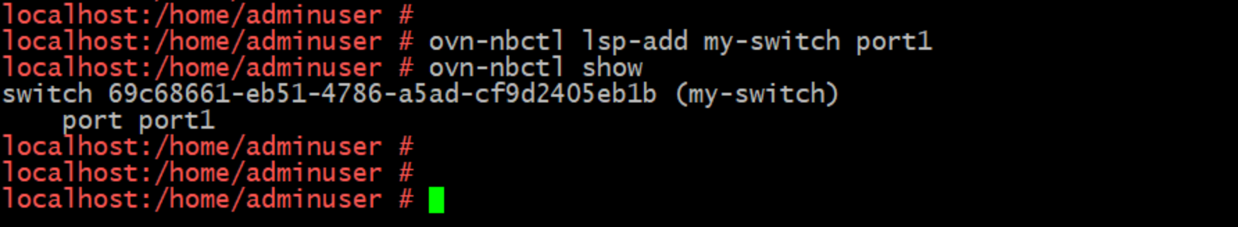
You can see we now have a switch called 'my-switch' with its first port attached to it.
Additional options for Logical Switches and Ports
We can configure additional options on our switch and ports based on our needs. Some of these commands are directly available as methods in ovn-nbctl, while others involve executing database queries (still using ovn-nbctl). The examples below will illustrate the differences.
Adding a subnet to a switch (for use in DHCP)
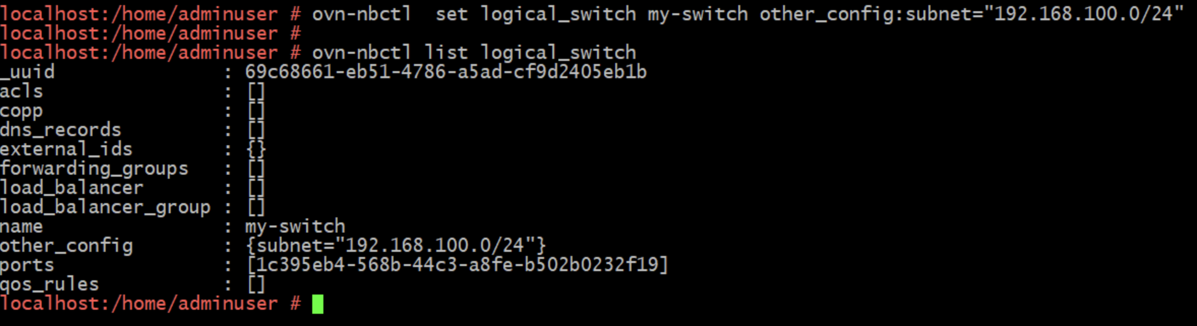
Note the 'set' / 'list' elements in the commands above. These are database queries, against the logical_switch table as opposed to running something like ovn-nbctl lsp-set-addresses method below.
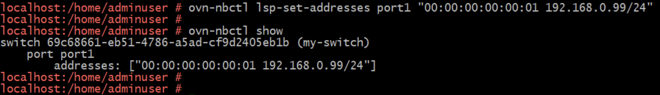
Setting addresses for a switch port
The man page documentation for ovn-nbctl is pretty easy to follow and you can also look up the commands on the OVN documentation site.
Logical Routers
Connecting Logical Switches to each other and to external networks via Logical Routers involves a few steps. First, you define the router, then add ports to it, and finally, connect those ports to the switches. This process can feel a bit redundant.
Projects like LXD and MicroOVN can save a lot of time, even if the underlying configurations are not entirely clear.
The diagram below illustrates a couple of switches interconnected by a Logical Router.

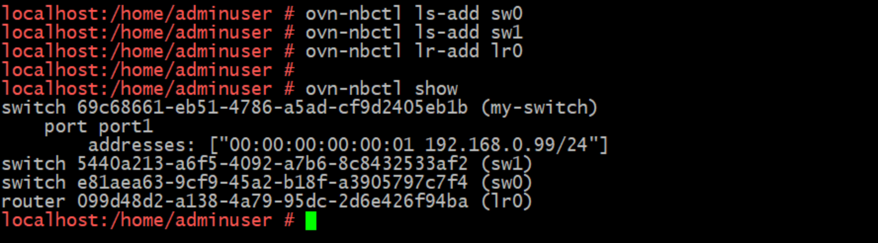
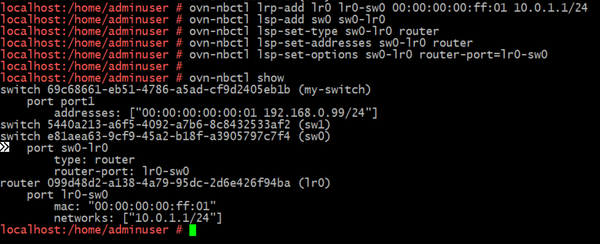
Let's start by building out Logical Switches sw0 and sw1 and Logical Router lr0.
Now let's connect sw0 to lr0 by defining the first Logical Router Port, I have to set a MAC address and IP for this port that sits in the address range I plan to use for devices on sw0 (10.0.1.0/24).
And the same to connect lr0 to sw1, this time making sure to assign a different MAC and an IP in the range I'm planing to use for devices connected to sw1 (10.0.2.0/24).
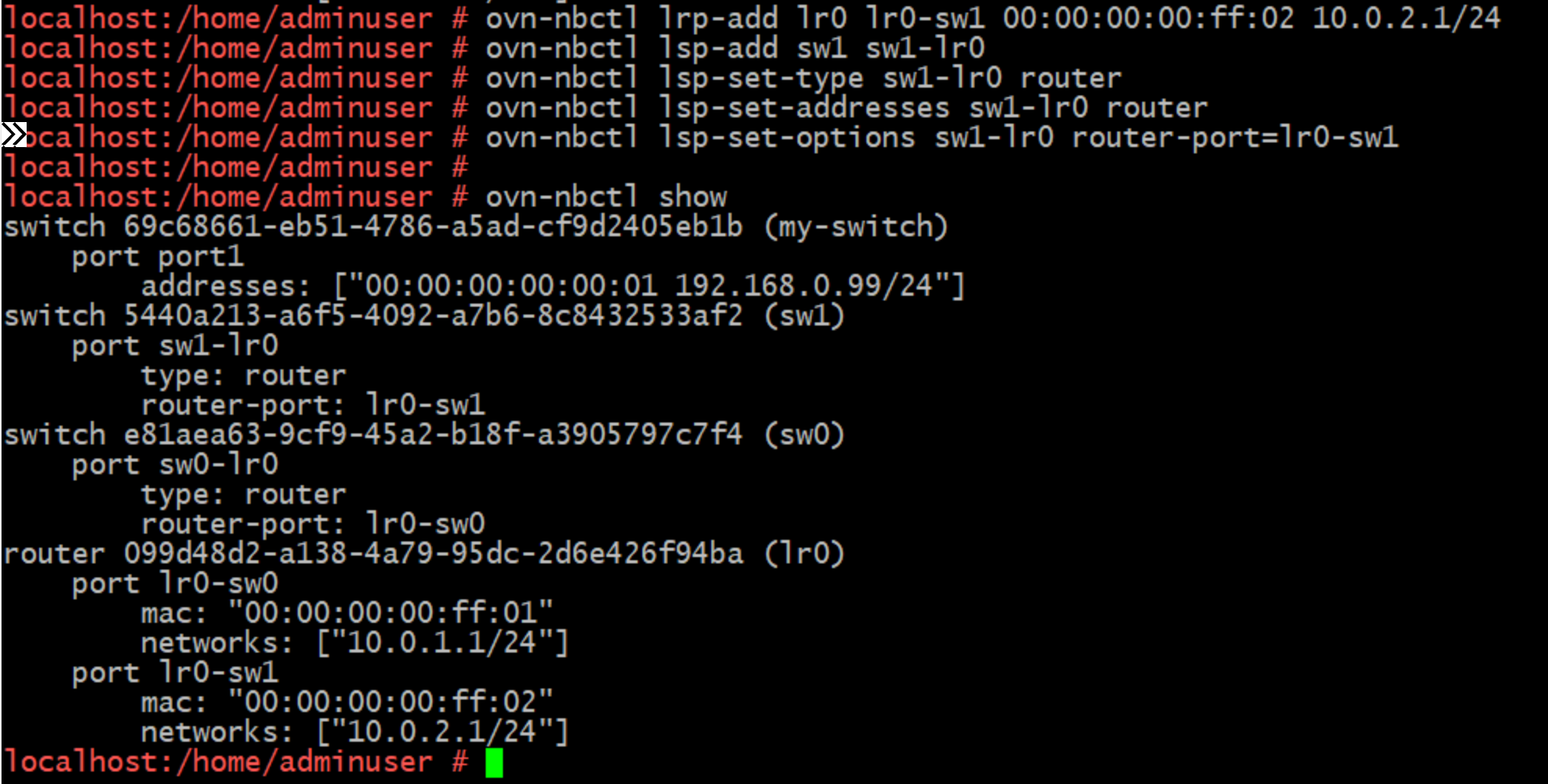
That's a straightforward example, but it should serve as a good introduction to the standard concepts of creating and connecting virtual networks using OVN. Note that I haven't specified which hosts to apply this configuration to, as our ovn-controller daemons handle that automatically for their local chassis.
Chassis
New terminology alert! Before we move on to the final aspect I want to cover—the dreaded uplink (it was dreaded for me because it took forever to peel back the layers of LXD 😄)—let's explain "chassis."
Each Libvirt host participating in the SDN is registered in the Southbound DB as a chassis. This is simply a representation in the database of a host running ovn-controller and, of course, Open vSwitch. You can list all the chassis using the ovn-sbctl show command.
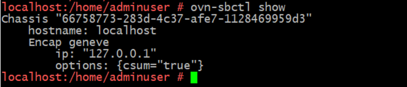
As you can see in the environment I am pulling these commands from, which is standalone, I have one chassis registered. In an HA setup you are going to need at least 3, and an odd number thereafter in order to maintain high availability.
Note also the super helpful UUID that's been generated and registered in my lab. If this was a large environment that would be hard to work with so in our walk through we we will be setting the system-id properly.

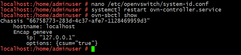
All you need to do is edit /etc/openvswitch/system-id.conf (on SUSE that's the right location but it could be different on Ubuntu/others), comment out the generated UUID and replace it with whatever helpful ID you want.
Restart ovn-controller and you'll find the Chassis registration updates, and of course you could set this before configuring ovn-controller to register with ovn-northd.
Uplink and external network connectivity
Reflecting on the fact that all our VMs are connected to br-int, it's important to note that br-int isn't actually connected to any physical ports in the chassis. While we can create switches and establish connectivity within our SDN, we can't yet communicate with anything outside of it, not even the host chassis a VM is running on.
To achieve this, we need to create an uplink network to connect one or more logical routers to our physical network. These are called Gateway routers, and this is where the Chassis becomes important as we need to schedule or assign Gateway routers to a chassis.
However, technically, we don't need to do this. For instance, LXD uses a 'distributed' router where the router port connecting to the uplink network is distributed across every chassis. This has several advantages, such as high availability and evenly distributed load across each chassis running a VM connected to a logical router sending data to the uplink.
On the downside, this means connecting every logical switch to the uplink, which might not always be desirable. It also requires opening up our provider network more than necessary and complicates NAT relationships, which are simpler to manage with a centralized gateway router.
The alternative to a distributed router is a Centralized gateway router, scheduled on specific chassis in either an HA or non-HA model. For HA, we can assign priorities to the chassis to help distribute the load.
Wrapping up
In part 6, we will delve into the provider bridge in detail. Part 4 is already quite extensive, and I still need to set up a lab. Hopefully, this post has covered some basic Layer 2/3 concepts and laid the groundwork for the deep dive in part 5, where I'll explain how OVN and OVS collaborate to provide uplink connectivity.
Ducksource Newsletter
Join the newsletter to receive the latest updates in your inbox.


)